If you are new to electronics, but you really want to create your first circuit on a printed circuit board, read the following tips to get started.

If it is really the first time that you try to make an electronic circuit, take my advise: start with a simple small circuit.
The best circuit designs can be found online, or in old-fashioned books ;-). Nice filters, powerful amplifiers, new microphone pre-amps, oscillators and much, much more circuits can be found. But if you do found this great circuit, HOW do you proceed?
1. First of all, gather all information about the components used in the circuit. Every component in electronics does have it’s own ‘user-manual’ or data-sheet. In this data-sheet you will find all important information like the general description of the component, the pin-out (= which pin has what kind of function), the power-supply connections, the min/max used current/voltage, the size etc. You can find this data-sheets online, by typing the type number.
2. The best way to build and test your first circuit is on a so called ‘bread board’ (see photos). With this board you can easily connect the components and create your circuit, without having to solder them. A breadboard consists of horizontal and vertical lines of ‘clamps’. Checkout the example below. You can see a 9V battery connected to a breadboard, powering a single led through a resistor
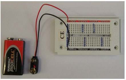
Breadboard 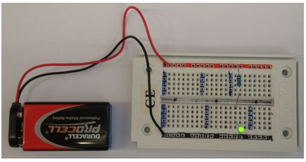
Breadboard with connected LED
When you start building your circuit, start with routing the power supply lines (the battery). So start with all the GND connections for example. After that, connect all the +V connections. If you are sure these are all connected, continue with the rest of the connections.
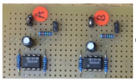
Component side 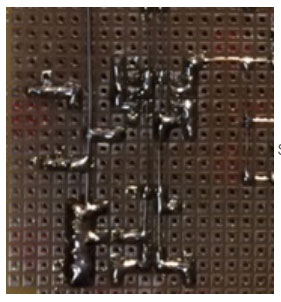
Soldering side
When you are finished, you have to apply the power. If the circuit works: Well done! But what if the circuit does not work? What do you do? Well, first of all, disconnect the power and take a good visual check:
a. All components connected the right way?
b. The polarity of the capacitors?
c. The pin 1 of the chips (IC)?
d. The polarity of the diodes?
e. The base, collector emitter of the transistor?
f. The value of the resistors?
g. Solid wire connections, no short circuits somewhere?
h. The capacity of the battery still ok?
Try to divide the circuit in smaller parts and test them separately. So disconnect some components and check if you get these parts of the circuit to work. For testing a circuit you really need a multimeter. Connect the power (battery) again and measure whether your power supply is still the right value (DC Voltage). If you have a short-circuit for example, the value of the power supply will be very low and a battery could become hot!
For more advanced testing you will need a sine wave generator (ac generator) and an oscilloscope to really see what happens inside your circuit. You are welcome to drop by the EWP and get some help with the problem in your circuit.
Well, let’s say your circuit is working great. Now you have to present it to your teachers or you have to do an on-stage performance with your new toy/instrument. What to do?
The circuit on your breadboard is very fragile and absolutely not stable. The next step is to solder your circuit on a experimental printed circuit board. With a board like this you can place your components on the ‘component side’ and solder the pins of the components on the ‘soldering side’. You have to inter-connect all the pins yourself.
A circuit that has been build on a board like this can work for a very long time and is very stable. We call this a prototype board. You only make one (or a few) versions of your circuit.
Suppose
all your friends say:” Wow, cool!, I also want to have one”. Or your
circuit really has to be build a lot of times, than you have to design a
complete Printed Circuit Board, or pcb and send your design of to a factory where they can produce your pcb. You can design your own PCB with (for example) Eagle Cad software.
Hope you make your (first) circuit soon!
Good-luck.